The first version of the hardware was a very good start, I could use and verify many components and features. However, I found many bugs and improvements here and there were necessary !
The first problem was the bandwidth used by the 2 OLEDS for the eyes. In order to have fast and smooth transitions on both display I boosted the bus clock from 400kHz to 800kHz. I know that normally the I2C high speed is 400kHz but from an article I read on HackaDay, the SSD1306 doesn’t actually need the ack to process the command from what I remember… Obviously the other sensors cannot follow that speed, that’s why I use now two I2C bus: one for the Eyes, the other for the rest of the sensors.
The second problem was the JTAG connector right under the TopCover bottom base, so the cover couldn’t fit properly…
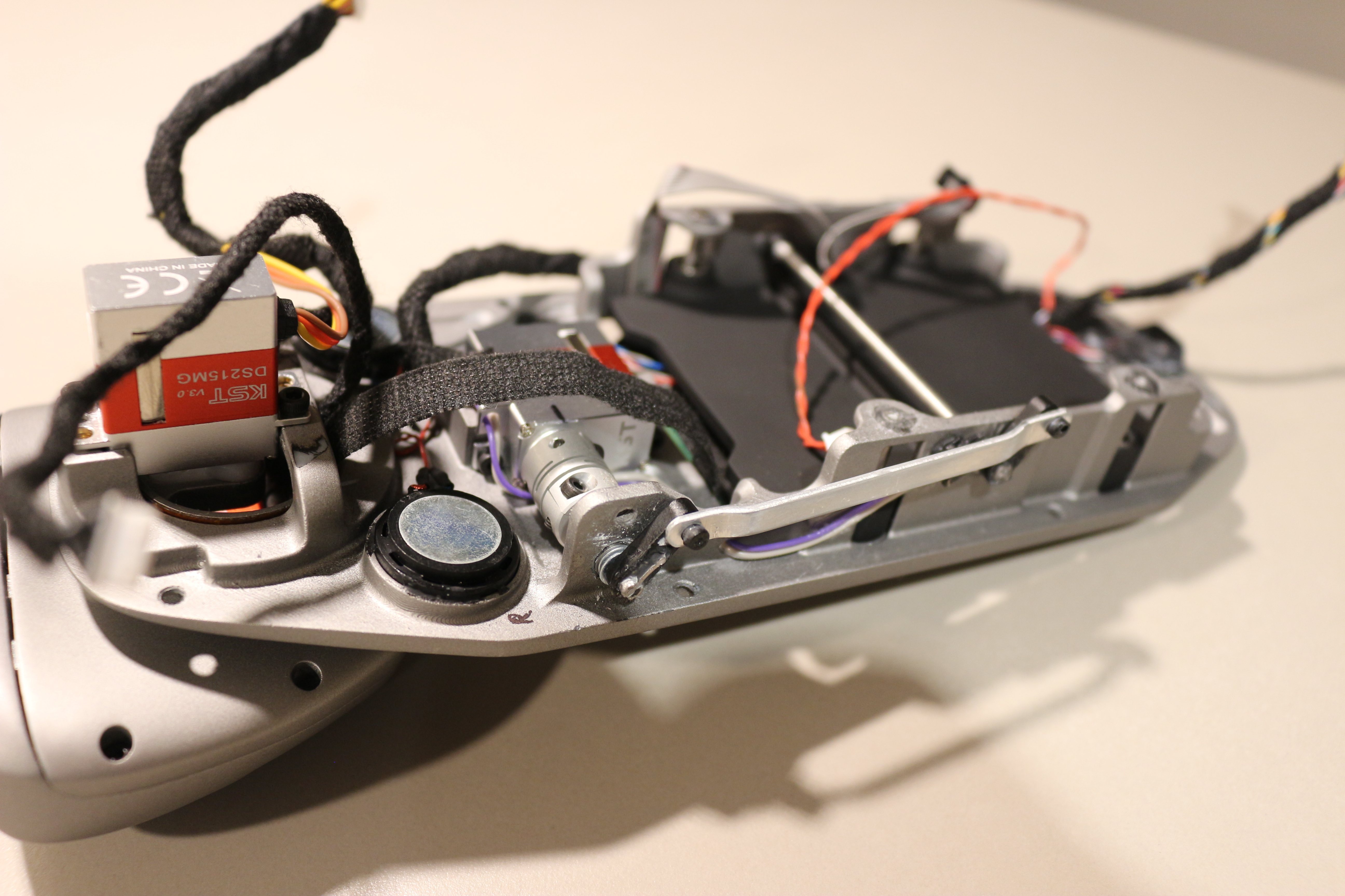
After some servos tests, I discovered to my surprise that when given a PWM, they are always making noise ! These servos are meant for Helicopters so I guess regarding the huge copter noise this is not disturbing… but for my purpose it is ! So after many test of PWM and software tricks I decided that the most efficient way was to add am MOSFET to the servos power supply. With this solution I only power the servo when they need to move, the rest of the time they are OFF (which is also good for power consumption)
I also improved the cooling of the main PSU by adding thermal pads beneath the MOSFETs and by adding a “venturi hole”. The wind tunnel uses a radial fan just on top of the PSU, but as it is a radial , it blows air directly towards the tunnel output. As the area below the fan is closed, all the sucked air goes directly out and there is a “hot air pocket” below it. By adding a hole beneath, the air is also sucked form the bottom of the PCB and flows through the component this time !
I decided to get rid of the 10DOF IMU board… it was too bulky and after consideration I do not need a barometer neither a compass. The accelerometer and gyro are just what I need for stabilization, the rest would be gadget… So, I looked up a bit an found a nice inertial module from ST, the LSM9DS1. Yes, it has a compass, but I will not use it.
Concerning the 5V power supply, I still don’t know why it burned when I connected the battery, because the schematic and layout are correct, and when it burned, the use case was within the range of the component,. So it will require further investigation and hopefully it won’t happen again !
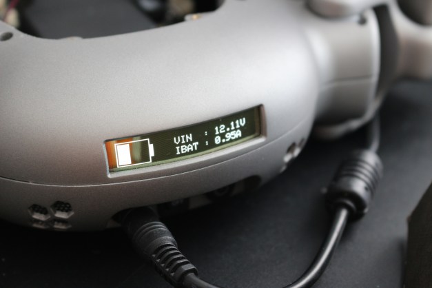
Last but not least, I redesigned the power management, which allows a smart shutdown from the MCU instead of the switch, which gives me more flexibility and control. So basically, when you flip the switch ON, it enables the 3V3 of the MCU. Then the MCU has control over the 5V and 9V of the motors with dedicated EN pins and via a general switch (MOSFET). When I want to shutdown the robot, I flip the switch OFF, this info is transmitted to the MCU and after a predefined timeout the robot will prepare its shutdown, move to its Park position then switch OFF completely (no current draw at all !)

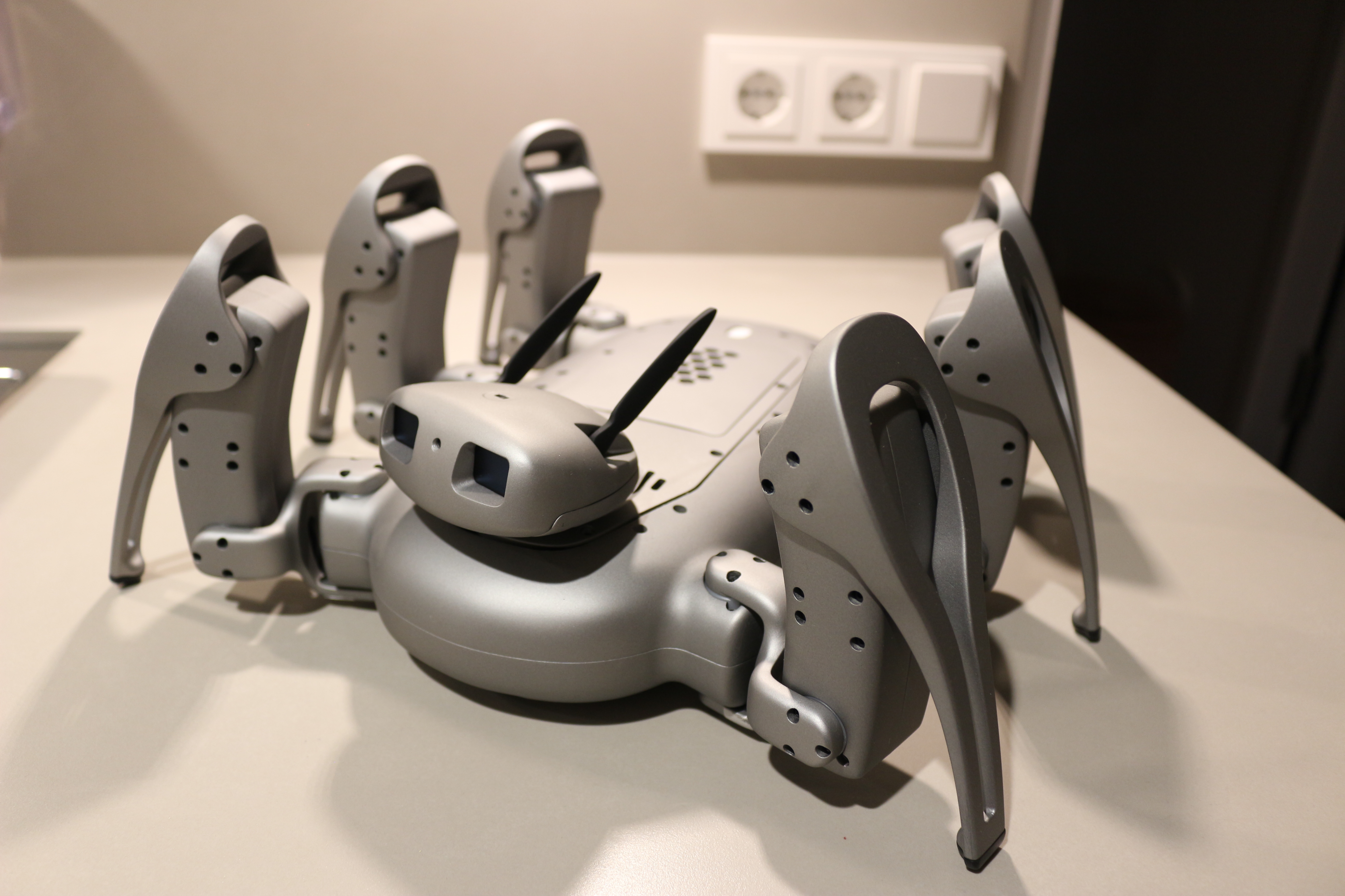
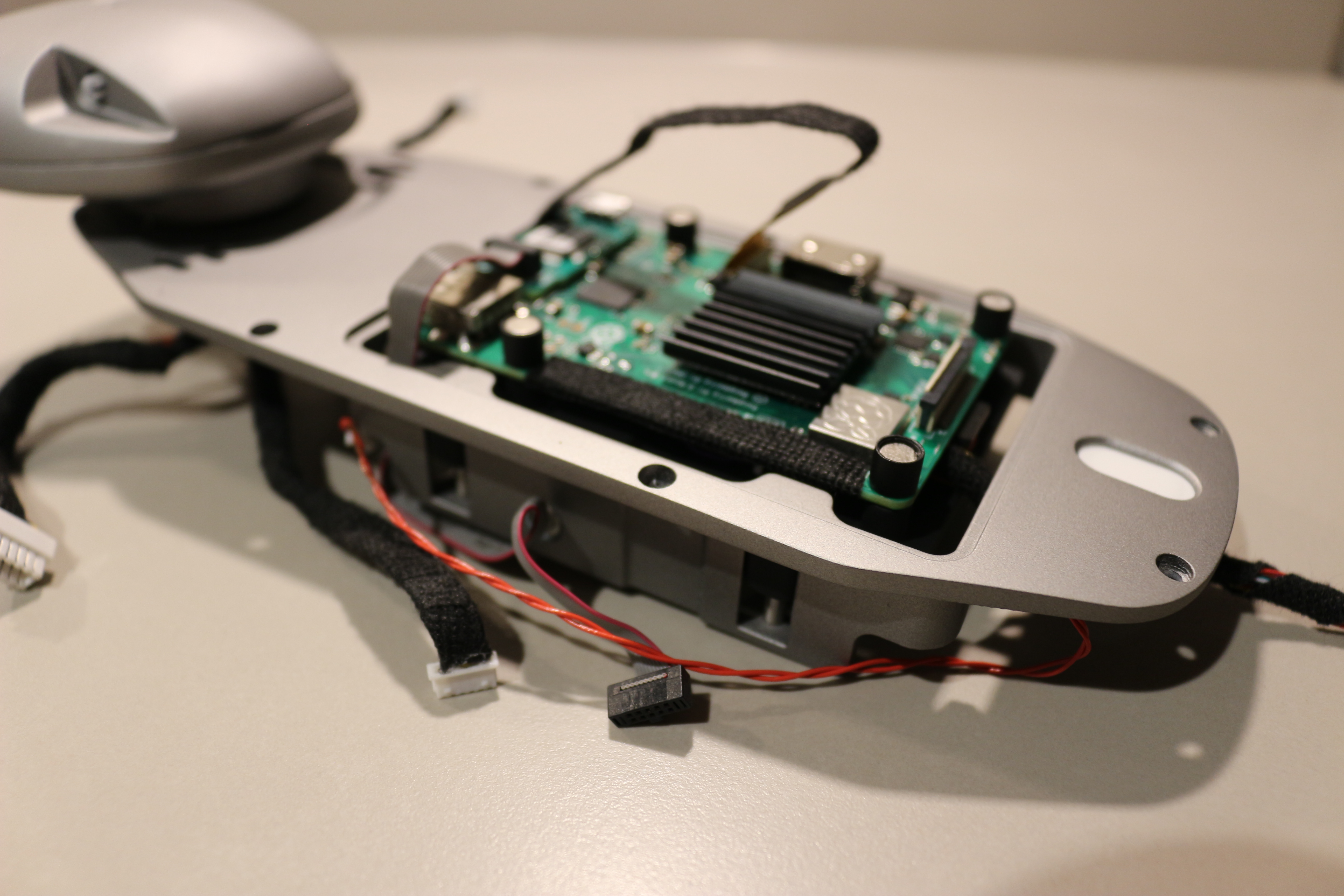
Top Side

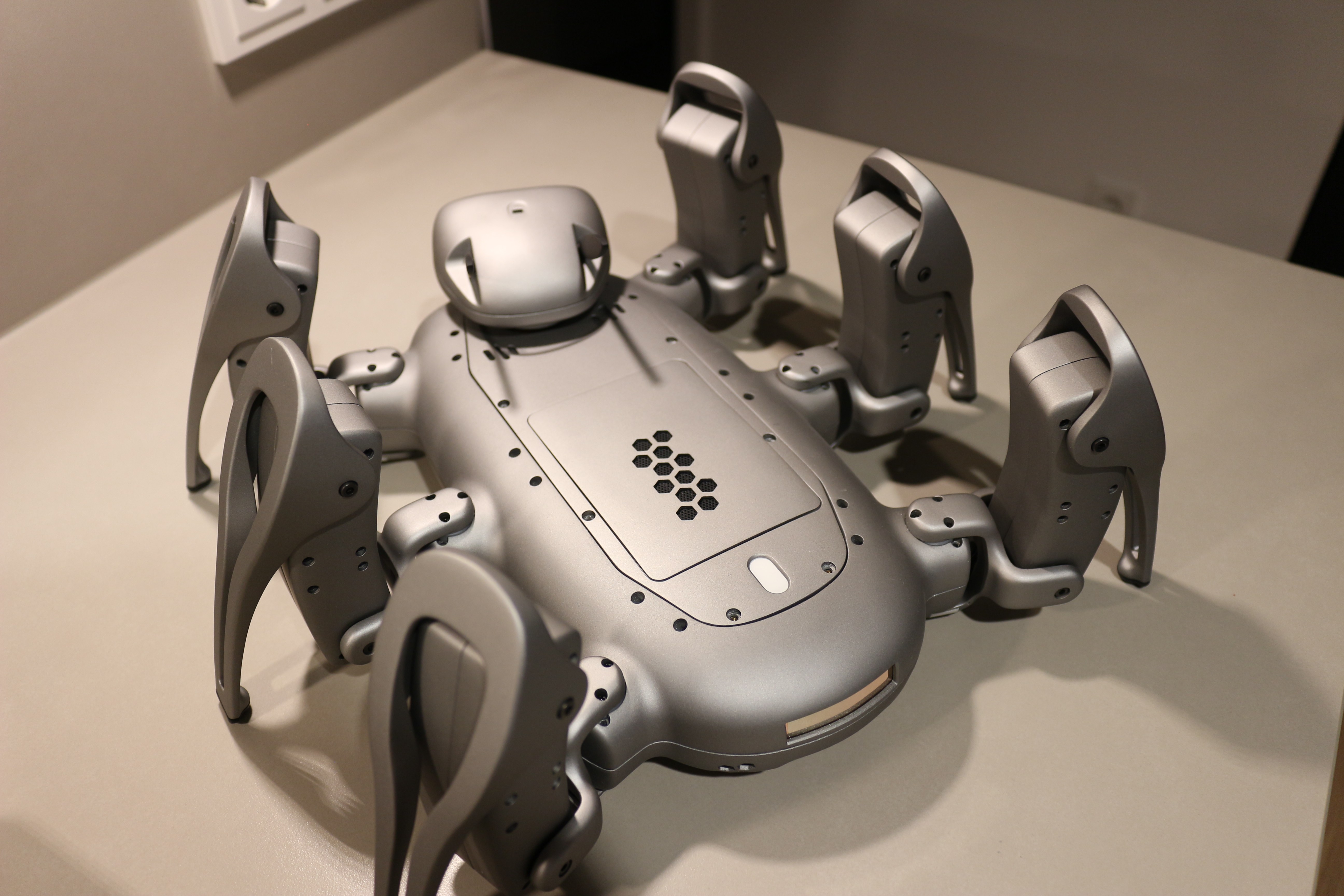
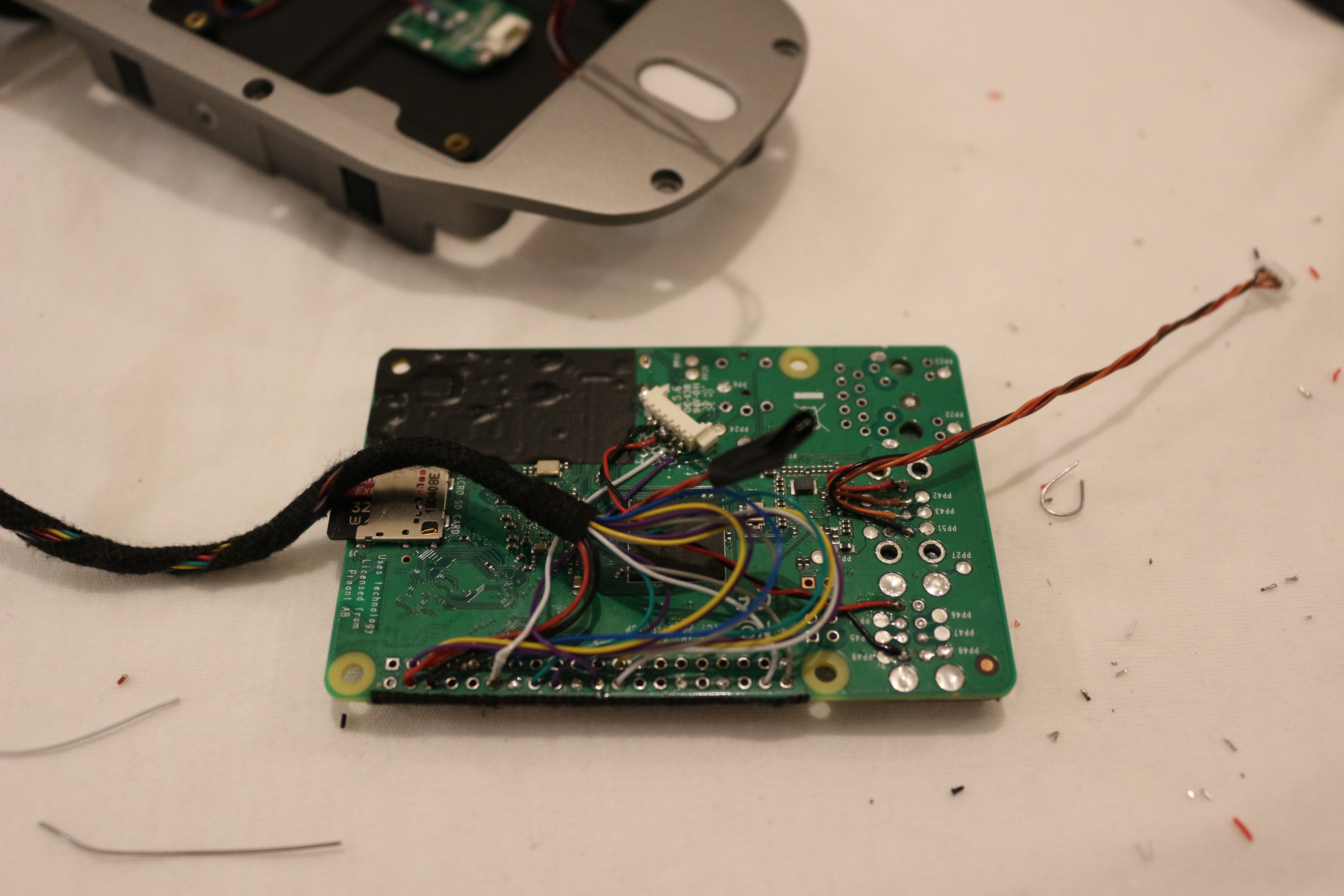
Bottom Side
The white thing you see on the bottom side is the NTC of the battery charger. I mounted it on strap which serves as a spring to press the NTC against the battery for temperature control 😉


