The development of features and functionalities is going pretty well. I’m now working on the mood and expression of the little guy. Now that the drivers are mainly done, this makes thing much easier 🙂
Animabot
All posts tagged Animabot
The development of Anima is continuing, I have been pretty busy writing the drivers for the Charger and the IMU, but I think I have a pretty good base to work on for now.
The current step is to have a homogen code and trying to make it as clean as possible, organize everything together, then I will start working on the servos !
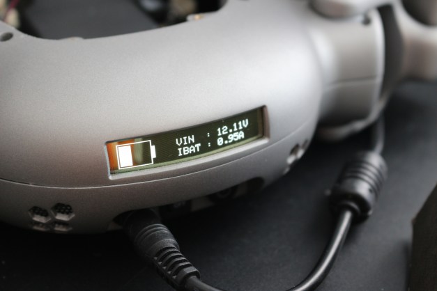
But for now, the OLED HMI looks promising 😉
Charging Menu 
Sensors data Menu
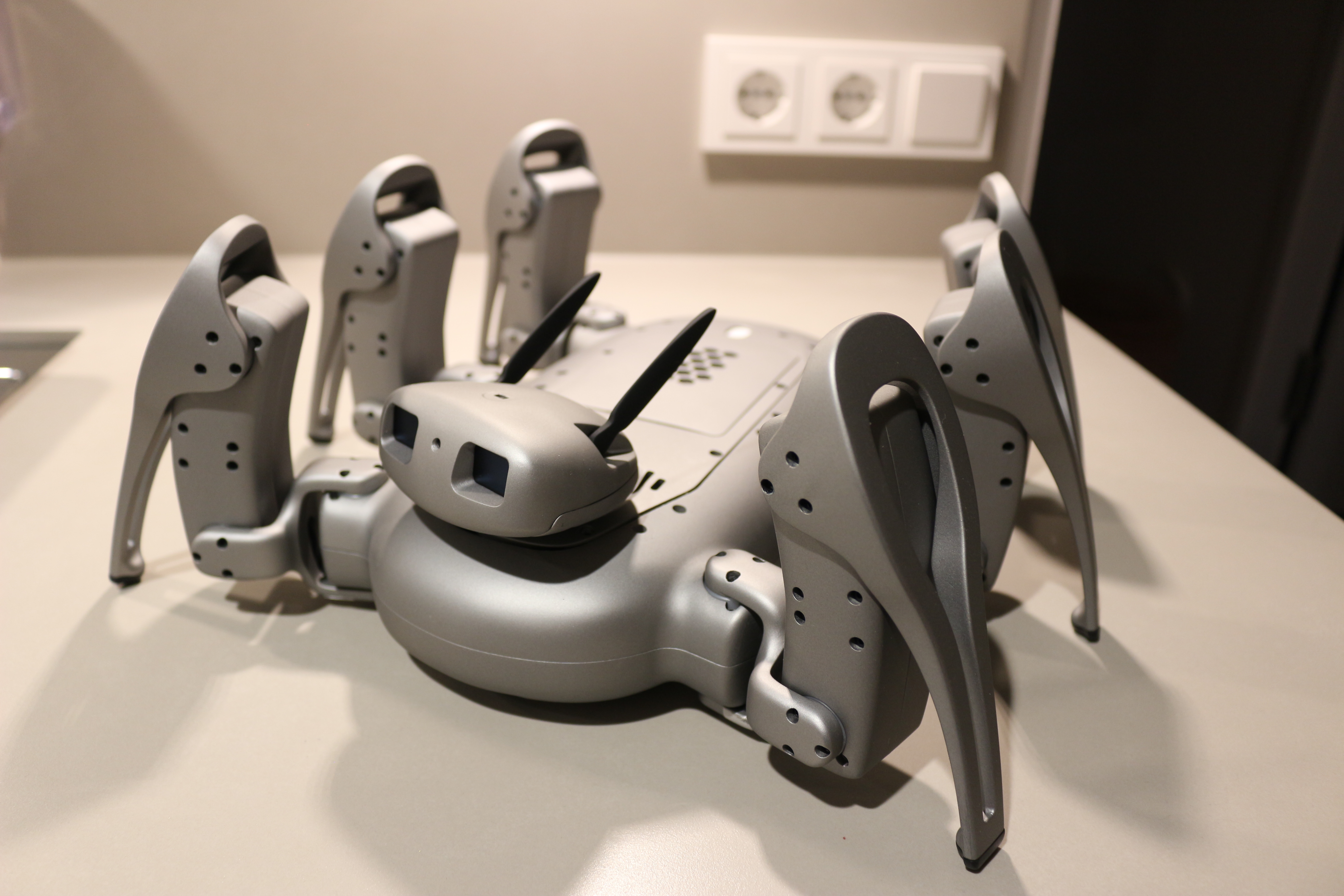
After one year of thinking, design, manufacturing and assembly, Animabot is almost ready to be properly programmed.
Not much to say for this post, except that I’m relieved I could do all within this year and that it worked out almost as planned 😀


Now, it is time to verify that all works, then I will continue to write the missing drivers and subroutines before working on the gaits, behavior and so on…
Stay tuned 😉
After weeks of testing and debugging, I think that the motherboard is finally ready 😀 I had some trouble with the charger which wasn’t communicating nor charging… The reason was simply a bloody wrong capacitor value…. but now it is fixed and working like a charm !
I also discovered some issues on the Servos power supply. Basically, it was not regulating well and completely not handling any load… So, I fixed that as well and did some extensive tests. Now, I’m proud to announce that the power supply has been tested with a continuous load of 16A at 7.6V (8A per channel) for 1 hour without any issue ! the temperature didn’t exceed 60°C (without fan).
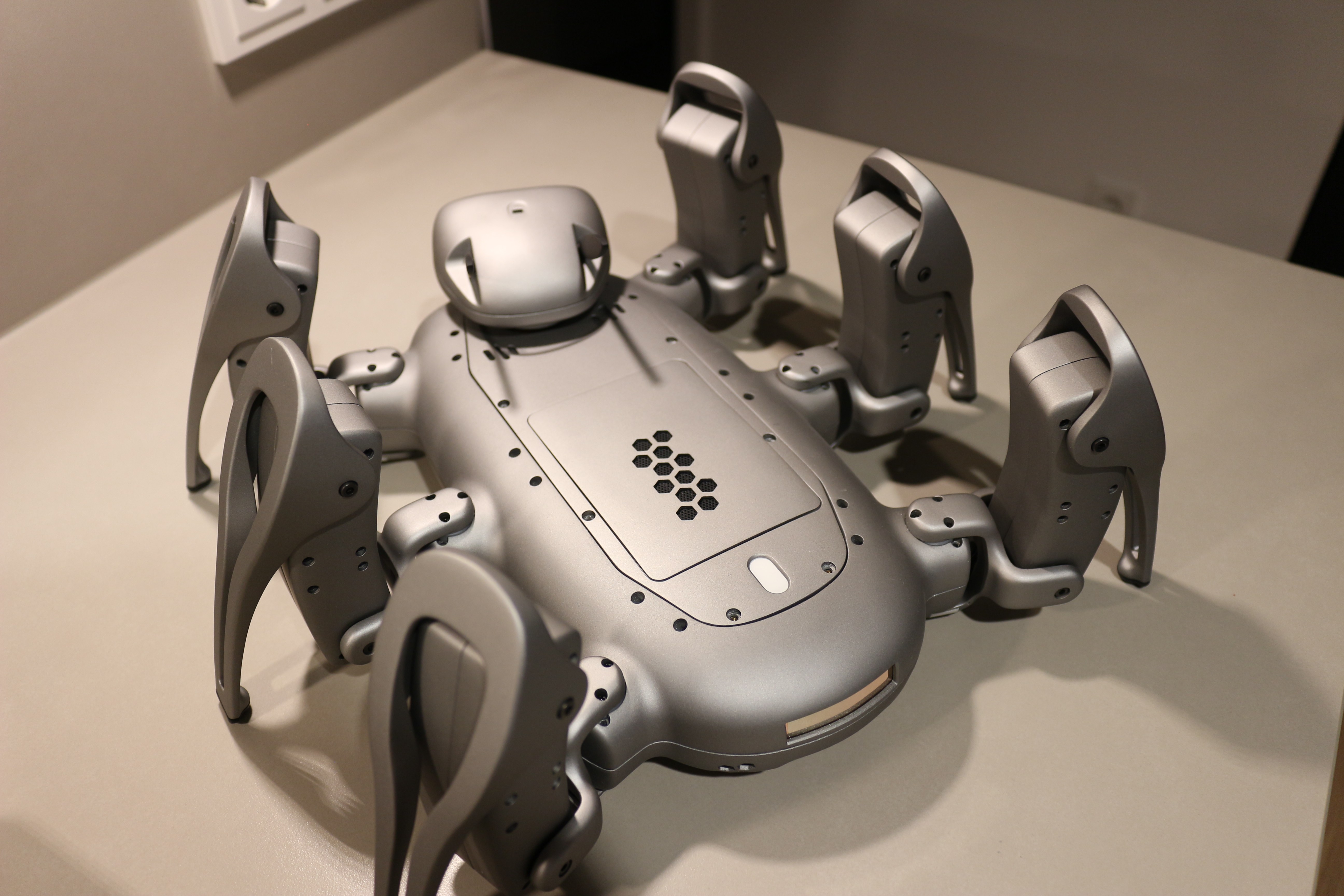
So now that all errors are solved, I installed the motherboard where it belongs, and here are the results :

All populated !

Servo Power Supply (LM25119)

Battery Charger (LTC4015)

Motherboard installed

Power Connectors

Assembly Overview
The first version of the hardware was a very good start, I could use and verify many components and features. However, I found many bugs and improvements here and there were necessary !
The first problem was the bandwidth used by the 2 OLEDS for the eyes. In order to have fast and smooth transitions on both display I boosted the bus clock from 400kHz to 800kHz. I know that normally the I2C high speed is 400kHz but from an article I read on HackaDay, the SSD1306 doesn’t actually need the ack to process the command from what I remember… Obviously the other sensors cannot follow that speed, that’s why I use now two I2C bus: one for the Eyes, the other for the rest of the sensors.
The second problem was the JTAG connector right under the TopCover bottom base, so the cover couldn’t fit properly…
After some servos tests, I discovered to my surprise that when given a PWM, they are always making noise ! These servos are meant for Helicopters so I guess regarding the huge copter noise this is not disturbing… but for my purpose it is ! So after many test of PWM and software tricks I decided that the most efficient way was to add am MOSFET to the servos power supply. With this solution I only power the servo when they need to move, the rest of the time they are OFF (which is also good for power consumption)
I also improved the cooling of the main PSU by adding thermal pads beneath the MOSFETs and by adding a “venturi hole”. The wind tunnel uses a radial fan just on top of the PSU, but as it is a radial , it blows air directly towards the tunnel output. As the area below the fan is closed, all the sucked air goes directly out and there is a “hot air pocket” below it. By adding a hole beneath, the air is also sucked form the bottom of the PCB and flows through the component this time !
I decided to get rid of the 10DOF IMU board… it was too bulky and after consideration I do not need a barometer neither a compass. The accelerometer and gyro are just what I need for stabilization, the rest would be gadget… So, I looked up a bit an found a nice inertial module from ST, the LSM9DS1. Yes, it has a compass, but I will not use it.
Concerning the 5V power supply, I still don’t know why it burned when I connected the battery, because the schematic and layout are correct, and when it burned, the use case was within the range of the component,. So it will require further investigation and hopefully it won’t happen again !
Last but not least, I redesigned the power management, which allows a smart shutdown from the MCU instead of the switch, which gives me more flexibility and control. So basically, when you flip the switch ON, it enables the 3V3 of the MCU. Then the MCU has control over the 5V and 9V of the motors with dedicated EN pins and via a general switch (MOSFET). When I want to shutdown the robot, I flip the switch OFF, this info is transmitted to the MCU and after a predefined timeout the robot will prepare its shutdown, move to its Park position then switch OFF completely (no current draw at all !)

Top Side

Bottom Side
The white thing you see on the bottom side is the NTC of the battery charger. I mounted it on strap which serves as a spring to press the NTC against the battery for temperature control 😉
After the Lower part, the Upper body was the logical next step. Actually, there was not much to do on this one… I started by installing the insert for the Top Cover, using the same method as before, which went flawlessly…

M2.5 Inserts

Top side

Bottom side
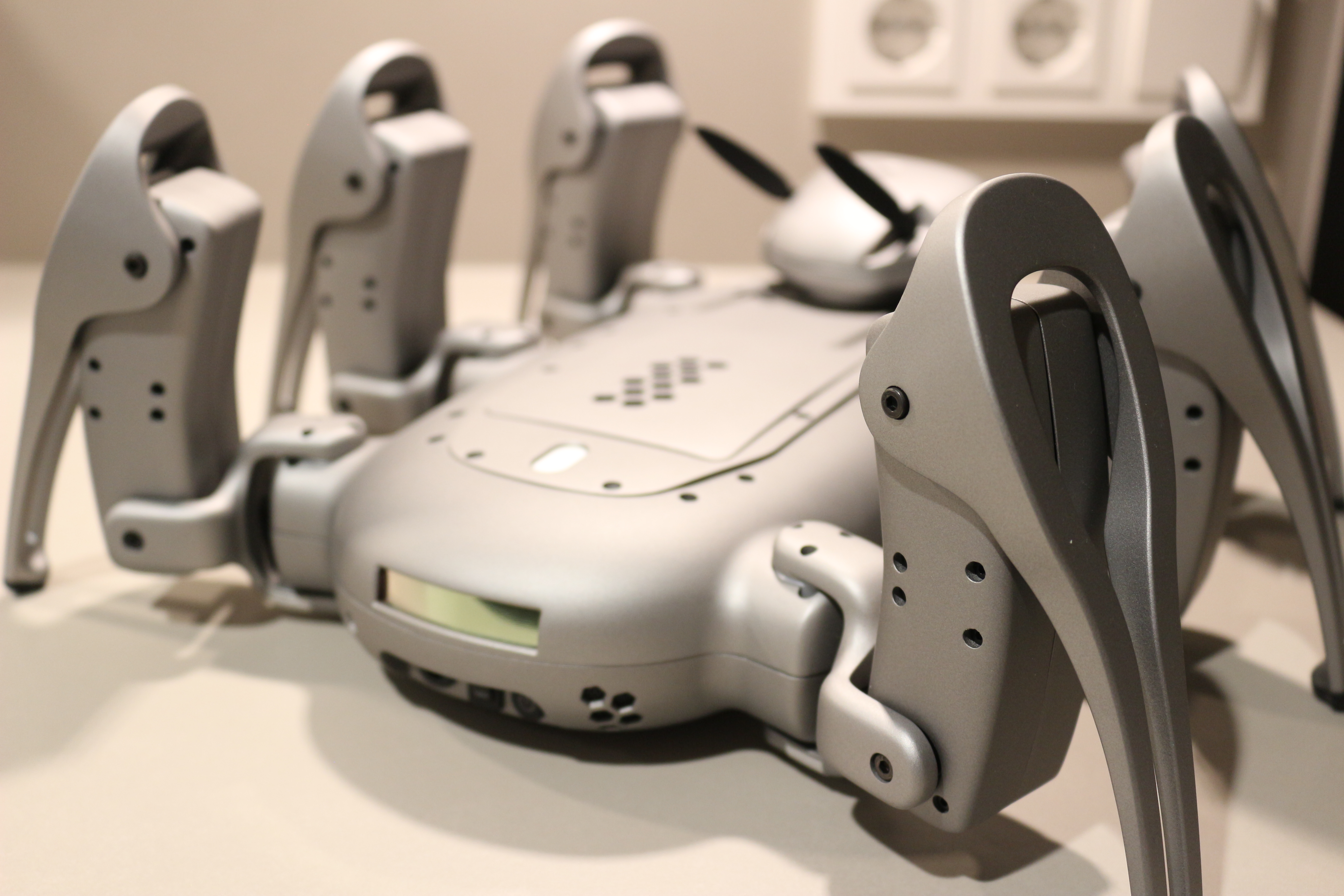
After the inserts, only the Flexible OLED display was left to install. I placed it first to see how the active area will match the outline of the body,then, I simply added double sided tape on the inner frame and pressed it against. In order to protect it, I added some felt tape and it looks nicer as well 🙂
For the cable, I first wanted to use braided sleeve but it turned out to be too rigid on the connectors and bit tricky to do… so I opted for the automotive solution by wrapping the cable in automotive tape. This looks pretty neat and avoid rattling noise if the cable is moving against the body.

OLED placement

Mounting

Outside view
And voila! The result turned out to be much better than I thought, this curved display looks stunning ! I can’t wait to make a proper HMI and menus 🙂

Animabot´’s Logo

Some sensors values

Animabot´’s Logo
See you later for the Top Cover assembly !
After so many weeks of waiting, all Animabot’s parts are finally home !!!
I decided to start with the lower body assembly and then working the way up to the head. The legs will be the last parts to be mounted because I need to redo the PCB and the PCB should be mounted before the legs 😀 this, and also because I didn’t find the courage yet to disassemble the current version yet ![]()


The first I did was to check if the motherboard and the servos were properly fitting inside and yes they do! So from this, I started by mounting the screws inserts in place ( by using a soldering iron, then pressing gently them in the hole). Once this step done, I continued with the buttons on the rear panel which are inserted and glued (easy peasy) and placed the dust grid behind the air vents. To install them, I also used the soldering iron and kind of “soldered” to the inner side of the body (melted both together), the result is not particularly aesthetic but it’s easy and durable !

Rear Panel Connections

Rear panel connections

IR Telemeter

Motherboard placement check
Below the battery, is mounted the dock connector constituted of 2 concentric copper rings (no polarity inversion possible !) and also the dock sensor which is basically a simple magnetic switch (Reed switch). All this is isolated from the battery with some Kapton tape. Last but not least, the IR Telemeter is now fiercely mounted on the front. The switch on the very bottom is the battery kill switch which allows me to completely disconnect the battery from the system …. just in case… 😀

Rear Panel Test

Dock Connector and Reed switch

Rear Panel

Robot’s belly

IR Telemeter
Next Step will be the upper body 😉
Good news ! The body parts are done and on the way ! I’m really exited to see how Animabot will come along once assembled. For the moment, I’m still writing and testing the drivers of the Motherboard and testing all components…. So hopefully, within few weeks I will finish this, send a new motherboard to production and integrate it.
Now, let’s enjoy the beauty of SLA 3D printing with smooth finish :

Big Puzzle

Upper Body


Lower & Upper Body Interior
")
Some internal parts

Lower Body
He is gonna be AWESOME !!!!
I finally received the rest of the components for the motherboard ! took me some hours to populate everything (QFN packages take a bit of time to solder when you are not used to 😀 )The smoke test passed for the Power supplies (7.6V, 5V) but I still have to test the battery charger… which gives me a bit of apprehensions because I don’t want to fry my battery ![]()
I will definitely have to make an improved version in the next few weeks to fix the following issues:
- Lack of thermal exchange for the PSU controller and MOSFET
- Change from 10DOF IMU board to a 9DOF IMU (LSM9DS1TR)
- Separate I2C bus for the Eyes (they use too much bandwidth forth rest of the sensors)
- Overall Routing & Layout improvements
- More detailled SilkScreen
But first I have to finish testing all the features and components to see if further modifications are required. But for now I’m pretty happy with the result, no big trouble. I did some thermal test and the PSU is around 40°C in idle mode without cooling and 35°C when the fan is active, even so the thermal dissipation of the component in not ideal and the fan is powered at 3V3 instead of 5V.

Motherboard in progress
As mentioned, I still have the rest of the features to test (around 15: Telemeter, Bluetooth, Charger, Raspberry Pi communication, Servos, etc…) so stay tune 🙂
The mechanical design is finished since few weeks, but I have been waiting some sample of the leg to check the tolerances, quality and color. This sample allowed to check the passage of the cable in the Coxa, the Tibia Cap (anti-slippery pad), servo mounting, etc..
I’m glad I ask I did that before the complete manufacturing because I found several issues. The passage for the cable needed to be deeper to protect it, the Pad was too small to hold in place properly and the color did not satisfied me totally… I’m still waiting for some more sample to compare and chose the final color !


Hopefully the samples will arrive soon, so I can order all the parts to assemble Animabot !

